

KYN28-12 Medium Voltage Switchgear OEM Manufacturing Key Considerations for Reliable Power Distribution
2026-10-30
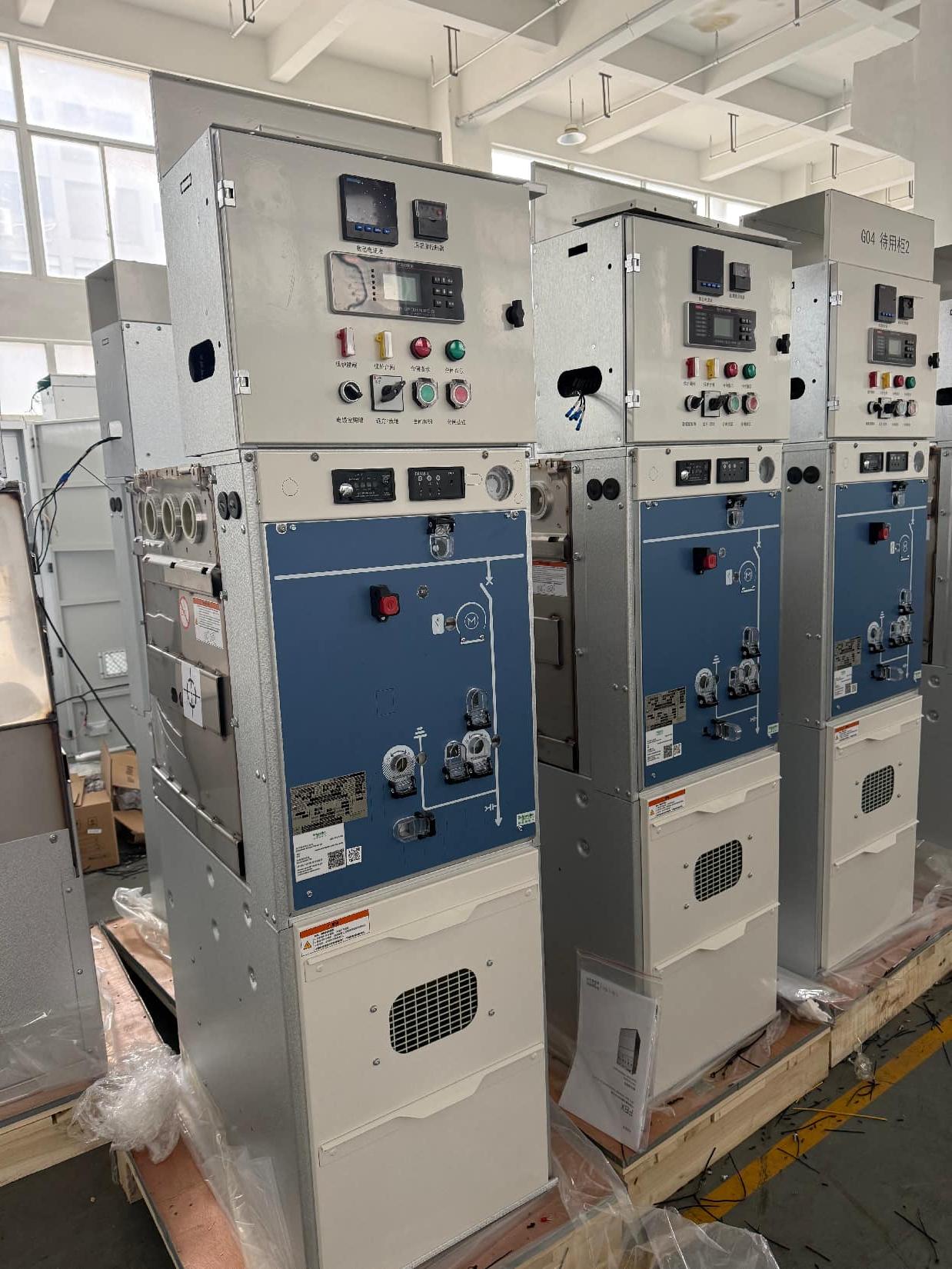
When a KYN28-12 medium voltage switchgear panel arrives on site, the difference between flawless commissioning and a costly outage often traces back to decisions made months earlier on the OEM floor. From busbar bending tolerances to vacuum interrupter alignment, the details that determine reliable power distribution rarely make it into a datasheet. MOLDVOLT has spent years inside those production lines, and this guide unpacks the practical checks that separate a dependable switchgear partner from an expensive gamble.
Enclosure Steel Thickness and Weld Quality Where Arc Containment Begins
Arc containment starts where the steel enclosure meets the electrode tip. If the gauge is too thin, heat bleeds through the wall and weakens the seam before it even cools. A minimum of 3 mm cold-rolled plate keeps the arc from breathing through the shell, though shops running longer duty cycles often step up to 5 mm. The extra mass isn't just for rigidity — it pulls heat away from the weld zone fast enough to stop burn-through on the back side.
Weld quality at this interface is less about penetration depth and more about continuity. A stitch weld that looks solid from outside can still leave a pinhole for arc flash to find. That's why continuous fillets along the vertical corners, plus a full-length weld on the bottom lip where the floor pan meets the side wall, matter more than a pretty cap. If you can drag a pick across the inside corner and feel a ridge, that's a stress riser waiting to crack under repeated heating cycles.
For enclosures that see stray slag or spatter, a backing strip of 1.5 mm copper behind the primary plate adds a sacrificial layer without changing the external footprint. It also gives the welder a visual cue — once copper shows through the root pass, you know you've hit the containment boundary. That simple check has kept more than one custom cabinet from becoming a firebox on the third shift.
Busbar Joint Surface Prep and the Hidden Variable Behind Contact Resistance
Busbar joint surface preparation often gets treated as a simple cleaning step, but the real story is far more subtle. Even a visually smooth copper or aluminum surface carries microscopic peaks, embedded oxides, and a thin film of moisture or grease. When two busbar faces meet under bolt pressure, only a fraction of the apparent contact area actually conducts. The rest is separated by air gaps or non-conductive layers. Proper prep—wire brushing, solvent wiping, or abrasive pad finishing—removes these barriers, but the sequence and timing matter. If the surface is prepped too early and left exposed, oxidation starts rebuilding within minutes, quietly raising the joint’s contact resistance before the first load is ever applied.
The hidden variable behind contact resistance is rarely the material itself; it is the microscopic condition of the interface. Two identical busbar joints can measure differently because one was buffed parallel to the current path and the other was scratched randomly. Directional finishing aligns more conductive peaks, while circular sanding can leave swirl patterns that trap debris. Another often-ignored factor is the type of cleaning cloth: some leave a silicone residue that mimics a clean surface but acts as an insulator. Even the humidity in the prep room changes the oxide growth rate on bare copper. Until these conditions are controlled, the measured resistance will keep drifting, making routine torque checks misleading.
To stabilize contact resistance, prep must be seen as a short-lived window, not a fixed state. The best practice is to finish the surface, apply an approved joint compound or antioxidant immediately, and bolt the joint to final torque within minutes. This limits re-oxidation and fills the remaining microscopic valleys with conductive material. Joint compound alone cannot rescue a surface that was never properly prepared, just as perfect prep cannot survive a delayed assembly. The hidden variable is time plus environment, acting on a surface that looks clean but is electrically unfinished.
Copper Purity Versus Plating Thickness Under Short-Circuit Stress
When a short-circuit event strikes, the interplay between copper purity and plating thickness becomes a silent battleground for conductor survival. High-purity copper, typically above 99.99%, contains fewer grain-boundary oxides and reduced electron scattering centers, which lowers intrinsic resistivity and helps dissipate the sudden thermal surge more uniformly. However, under extreme current density, even the purest copper can undergo electromigration and localized melting if the plating is too thin to act as a thermal buffer. A thinner deposit concentrates the Joule heating into a smaller cross-sectional area, raising the peak temperature at the interface between the copper and its substrate, which may accelerate delamination or void formation long before the bulk material fails.
Plating thickness, on the other hand, does not simply scale with resilience. A heavier layer of copper can indeed absorb more energy before reaching a critical failure temperature, but it also introduces greater mechanical stress due to differential thermal expansion. When the short-circuit pulse is brief yet intense, rapid heating followed by quenching can crack a thick, less pure plating because impurities tend to segregate at grain boundaries and act as crack initiation sites. In contrast, a thinner but higher-purity copper layer may flex without fracturing, allowing the substrate to share the thermal load more effectively. The sweet spot often lies in a moderate thickness paired with elevated purity, where the plating can withstand the thermal shock without compromising its structural integrity.
Field data from accelerated life tests on printed circuit boards reveal that failures under short-circuit stress rarely follow a linear rule. A plating of 25 microns with 99.999% copper can outperform a 50-micron layer at 99.9% purity, especially when the stress is repetitive. The reason is twofold: first, higher purity reduces the localized resistive hotspots that seed thermal runaway; second, the thinner, cleaner layer offers fewer grain-boundary traps for vacancy accumulation, delaying the onset of micro-voids. Engineers facing tight design constraints should therefore prioritize copper purity over raw thickness when short-circuit endurance is paramount, and reserve thicker deposits for cases where mechanical wear or corrosion dominates the failure mode.
Vent Path Geometry and Pressure Relief Flap Calibration for Internal Arc Faults
Proper sizing of the vent path is not a matter of copying a standard cross-section from a catalog. In practice, the geometry must account for the directional nature of arc plasma, the initial pressure wave, and the thermal expansion that occurs within milliseconds. A straight duct with uniform area may reflect pressure back toward the enclosure, so the design often incorporates a gradual transition or a deliberate expansion chamber. The placement of bends, if unavoidable, should follow a radius that keeps the flow attached rather than creating a stagnation zone.
Pressure relief flaps introduce another layer of calibration: their mass, hinge friction, and preload determine the point at which they begin to open. A flap that is too heavy will delay venting until the enclosure has already experienced mechanical stress, while one that is too light may open during normal pressure fluctuations. The calibration sequence typically involves both static and dynamic tests, where the flap's opening angle is measured against a known pressure ramp. Small adjustments to the hinge stop or counterweight can shift the response curve by several milliseconds, which is critical for protecting busbar joints and cable terminations.
Field experience shows that the combined geometry and flap calibration should be validated at the lowest and highest expected fault currents. At low currents, the arc may not generate enough pressure to fully clear the vent path, leaving hot gases trapped near the arc origin. At high currents, the flap can reach its mechanical limit and create a secondary restriction. A useful refinement is to install a pressure transducer near the flap hinge and log the pressure decay during the first 100 ms of the event, then adjust the vent cross-section or flap preload until the decay curve consistently avoids resonant peaks in the enclosure.
Withdrawal Mechanism Alignment Tolerances That Prevent Breaker Misinsertion
Precision in the withdrawal mechanism starts with how the breaker's primary and secondary disconnects are guided into their fixed counterparts. The alignment tolerances here are not merely about centering a moving carriage; they define the permissible lateral and angular deviation before insertion resistance becomes unsafe. For example, if the guide rails allow more than 0.5 mm of lateral play at the disconnect mating plane, a breaker of a different frame size can be forced partway in, jamming the racking mechanism and risking damage to both the breaker and the switchgear cell. Manufacturers typically achieve this by machining the racking screw support and the carriage guide channels as a matched set, with the interlocking key profile tied to the specific breaker rating.
A second layer of protection comes from asymmetric tolerance zones. Instead of a uniform clearance around the breaker's positioning pins, the design deliberately narrows the tolerance on the side corresponding to the auxiliary contact block. This means a breaker intended for a lower interrupting rating—whose auxiliary contacts have a different pin layout—will encounter immediate mechanical interference, not gradual binding. The racking handle will not turn past the first fraction of a turn, and the operator receives tactile feedback that the breaker is incorrect. This approach is far more reliable than color coding or label warnings alone, which can fade or be ignored under time pressure.
Field experience has shown that the most effective misinsertion prevention combines tight linear tolerances on the racking carriage with a stepped guide profile near the breaker's closed position. The final 10 mm of travel into the connected position uses a reduced clearance window—often less than 0.2 mm total—so that any breaker with a slightly different interlock plate thickness cannot complete the stroke. When a facility upgrades breakers across multiple voltage classes, verifying these withdrawal mechanism tolerances with a go/no-go gauge and a test racking cycle becomes a standard part of the acceptance procedure, ensuring that only the correct breaker can ever reach the fully connected state.
Factory Tests Worth Adding Beyond the Routine Dielectric Check
While the dielectric check remains a staple for catching gross insulation failures, it rarely reveals the subtle wear patterns that lead to field returns. A much better use of factory time is a dynamic load bank test with rapid step changes—not just a steady-state soak. Sweeping the load from 10% to 110% in three-second intervals exposes weaknesses in output filtering and feedback loop stability that a constant resistance test simply cannot. Pair this with a thermal imaging pass under full transient load, and you will spot hot spots forming around connector joints and busbar interfaces long before they become resistive enough to fail a routine hi-pot.
Another underused but high-value test is the controlled line disturbance simulation. Instead of relying on a single sag or swell at 90% and 110% nominal voltage, run a sweep of phase-angle-controlled dips from 0% to 80% residual voltage across all three phases. Log the unit's ride-through behavior and compare it against the design margins for hold-up time. Many units that pass a static dielectric test will shut down or reset during a 40% dip at 90 degrees—a condition that occurs regularly in industrial environments where large motors start across the line. Catching that at the factory costs pennies; missing it costs a service call and a damaged reputation.
Finally, add a sustained common-mode noise injection test on the control and communication lines. Inject a 2 kV, 100 kHz damped oscillatory wave between signal ground and chassis ground for at least 60 seconds while the unit is running at 75% load. Monitor for corrupted data frames, unexpected resets, or loss of PWM synchronization. Standard dielectric tests isolate power conductors but completely ignore the low-voltage control circuitry that is often the weakest link in a noisy plant. If the unit can survive this without a single missed CAN message or gate drive fault, it will survive almost any installation.
FAQ
The modular framework and withdrawable breaker truck allow manufacturers to rearrange busbar, cable, and control compartments independently. This flexibility helps adapt to varied busbar ratings or protection schemes without weakening the arc-proof enclosure or the mechanical interlocks.
We avoid relying on extrapolated type test data. Any non-standard layout goes through a certified internal arc test with the exact panel geometry, reinforced door hinges, and pressure relief flaps in place. Only after passing the required arc duration do we release the modified design for production.
Structural parts benefit from Aluzinc or stainless steel, while busbars should be silver-plated copper. For enclosures, epoxy powder coating with at least 500 hours of salt-spray resistance is a practical baseline. Anti-condensation heaters and IP4X venting also reduce moisture-related tracking failures.
The five-prevention logic depends on precise adjustment of the racking screw, earthing switch rod, and cable door interlock. If rod lengths are off by a few millimetres, the breaker may be racked while the earthing switch is closed or the door may open with live busbars. Mechanical verification of each interlock path is non-negotiable before electrical tests.
Use high-tensile bolts with Belleville washers to maintain contact pressure during thermal cycling. After jointing, measure contact resistance across each joint and compare with the busbar run baseline. For sliding contacts on the withdrawable truck, silver plating is preferred over tin to reduce oxidation and friction wear.
We run a partial discharge test at 1.2 times rated voltage on every custom panel. TEV or ultrasonic sensors help locate voids, cracks, or floating shields inside CT chambers and busbar sleeves. Anything above 10 pC in critical compartments triggers rework, because transport vibration often turns small defects into insulation failures.
The breaker's rated short-circuit current and creepage distance must match the switchgear assembly. More importantly, the racking travel and primary disconnect alignment need verification with a dummy busbar gauge. The breaker's mechanical interlock interface must also mate with the panel's racking mechanism without excessive play.
Beyond a visual check, include mechanical operation of breakers and earthing switches, main circuit resistance measurement, power frequency withstand test on main and auxiliary circuits, wiring continuity checks, and a functional test of protection relays with injected secondary currents. A sample panel from each batch should also undergo temperature rise or partial discharge testing if the busbar layout changed.
Conclusion
When an OEM takes on KYN28-12 switchgear production, the difference between a cabinet that contains an arc fault and one that fails often comes down to decisions made on the factory floor rather than the single-line diagram. Enclosure steel is a good starting point: 2mm cold-rolled sheet with inconsistent weld penetration can pass a visual check yet tear open under pressure, so weld quality has to be treated as part of the arc containment system, not a cosmetic detail. The same practical lens applies to busbar joints. Surface roughness and oxidation on contact faces quietly drive up contact resistance, and no amount of bolt torque can correct a poorly prepared joint. Under short-circuit stress, the debate between copper purity and silver or tin plating thickness is not academic; high-purity copper with a thin or patchy plating layer can still suffer localized heating and accelerated degradation at the joint interface.
Beyond conductors, internal arc performance depends heavily on vent path geometry. The pressure relief flap must be calibrated so it opens at the designed overpressure and directs hot gases away from the operator zone, otherwise the blast finds the weakest structural gap instead. Withdrawal mechanism alignment is another area where tolerances are too often treated as optional. A few millimeters of lateral play or a sagging guide rail can lead to breaker misinsertion, damaging primary contacts and creating a latent fault. Finally, factory acceptance should move past the routine dielectric check. Added tests—such as contact resistance measurement across every busbar joint, mechanical endurance cycling of the withdrawal mechanism, and a low-energy internal arc simulation to verify flap response—catch failures that normal power-frequency withstand tests will miss. These are the details that separate reliable OEM supply from a switchgear line that only looks compliant on paper.
Contact Us
Contact Person: Hellen
Email: [email protected]
Tel/WhatsApp: 86-13634205622
Website: https://www.voltcabinet.com