

TaC Coated Susceptors Top 10 Picks for Reliable Semiconductor Processing
2026-11-18
Most semiconductor processing failures don't start with a dramatic alarm; they begin at the susceptor surface. A slight unevenness in TaC coating, a weak edge bond, or inconsistent grain structure can quietly shift thermal uniformity and shorten preventive maintenance cycles. That's why selecting the right TaC coated susceptor is less about ticking a specification box and more about matching coating behavior to your actual process conditions. Below, we have narrowed the field to ten reliable options for CVD, epitaxy, and other high-temperature steps. Several stand out for dense, high-purity TaC layers and stable performance under repeated thermal cycling. If you're tired of replacing susceptors sooner than expected, this list points you toward designs that hold up. For deeper material and coating support, Semicorex offers practical guidance and production-ready solutions.
How TaC Coatings Keep Wafer Surfaces Clean in High-Temperature Chambers
At high process temperatures, chamber internals shed more than just heat. Bare graphite and quartz surfaces slowly degrade, releasing micro-particles and outgassed species that settle on the wafer. A tantalum carbide coating changes that dynamic by forming a dense, non-porous barrier that resists oxidation, halogen attack, and thermal fatigue. Fewer surface reactions mean fewer contaminants drifting toward the wafer, even under aggressive thermal cycling.
The coating also keeps by-products from finding a foothold. In deposition and etch environments, residues tend to accumulate on untreated walls, then flake off once film stress builds. TaC holds a stable, low-energy surface that discourages strong adhesion. Loose deposits are easier to purge, and the coating's grain structure stays intact longer, so particle bursts from spalling are largely suppressed.
Dimensional stability matters as much as chemical resistance. TaC maintains its mechanical integrity at temperatures where other materials begin to creep or micro-crack. That predictable behavior keeps chamber geometry consistent, reducing flow disruptions that can stir up particulates and carry them onto the wafer surface.
CVD TaC and Sintered TaC in Real Production Conditions
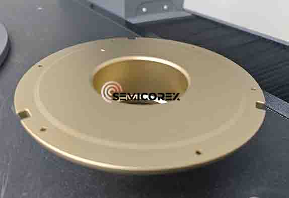
In production, the choice between CVD TaC and sintered TaC rarely comes down to catalog specifications. CVD TaC tends to be favored where a dense, conformal layer is needed on complex graphite fixtures, especially in MOCVD reactors running ammonia or hydrogen at temperatures above 1100°C. The coating follows the substrate surface and can seal porosity that would otherwise outgas or react. Sintered TaC, by contrast, shows up more often as standalone parts such as susceptors, crucibles, or liners, where the entire cross-section needs to resist carburization and thermal shock. Its behavior depends heavily on grain size and residual porosity from pressing and firing.
Under real thermal cycles, the differences become visible within weeks. CVD layers can develop microcracks if the underlying graphite expands unevenly, and once the coating is breached, attack moves laterally beneath the film. Sintered parts tend to fail more gradually: edges may erode, or a hairline crack propagates after repeated heating and cooling. Operators often prefer CVD-coated graphite when the part geometry is nearly impossible to machine from solid TaC, but they accept that coating thickness must be checked after each maintenance window. Sintered TaC is specified when mechanical loads are high or when any coating defect would be unacceptable for yield.
Cost calculations also shift once real production conditions are included. CVD TaC may look economical because it uses less tantalum, but recoating downtime and limited repair cycles can erase the initial savings. Sintered TaC carries a higher upfront material cost, yet it can survive longer in aggressive hydrogen environments if the sintering process leaves low closed porosity. In practice, many fabs run both forms side by side: CVD-coated graphite for large, intricate carriers and sintered TaC for small, high-stress components that are replaced on a fixed schedule rather than inspected and recoated.
Reading Thermal Uniformity Data Before Committing to a Susceptor
A susceptor can look nearly identical to another on a datasheet and still produce a different temperature profile once it is inside your chamber. Before settling on a design or replacement part, run a thermal uniformity check under conditions that resemble your actual process: same gas flows, same pressure, same wafer position. The numbers worth paying attention to are not just the average temperature but the spread across the wafer, the edge-to-center delta, and any repeatable cold spots that only appear after several cycles.
It helps to compare those readings against known good production data rather than relying on a supplier's generic uniformity map. Small shifts in pocket depth, coating thickness, or material blend can move heat away from the edge or hold too much of it near the center, and those effects often show up later in film thickness or resistivity. If the thermal profile does not stabilize within your normal conditioning window, that is a signal to pause before committing the susceptor to a production tool.
Microcracks and Delamination as Early Warning Signs
Microcracks often begin where stress concentrates: a sharp ply drop, a slightly oversized hole, or a resin-rich region near a radius. On their own, these small splits rarely look alarming, but they create pathways for moisture and oxygen, and under repeated loading they can link up into a delamination front. Their real value is that they appear well before global stiffness drops enough to be noticed in routine checks.
Delamination behaves differently depending on the loading direction. Opening loads tend to produce a clean separation, while sliding loads can grow slowly and leave rubbed, fibrous surfaces behind. In either case, the damage is often hidden between plies or beneath a surface coating, invisible from the outside. That is why tap tests, ultrasonic scans, and strain-based monitoring are used to catch it before it reaches a fastener line or free edge where repair becomes far more involved.
The message in these early signs is not that a structure is about to fail, but that the load path is changing. A local microcrack may relieve stress in one area while transferring it to adjacent material. Watching that shift, rather than simply counting cracks, gives a much more realistic picture of remaining life.
Matching Susceptor Dimensions and Coating Thickness to Your Reactor
Getting the susceptor geometry right is less about matching a catalog number and more about understanding the thermal footprint inside your chamber. The diameter, pocket depth, and edge profile all influence how heat moves from the heating elements into the wafer, so a dimension that works well in one reactor can create a noticeable temperature spread in another. Rather than relying on nominal chamber size, measure the actual hot zone and check the clearance between the susceptor edge and the chamber wall. That gap affects parasitic heating and gas flow stability more than it might appear on a drawing.
Coating thickness often gets treated as a minor variable, but it changes how the surface absorbs and releases energy. A thicker silicon carbide or graphite layer can smooth out short-term temperature swings, yet it also adds thermal mass and slows the ramp response. Too thin a coating tends to wear faster and can expose the underlying material, leading to local hot spots. The right thickness should reflect your reactor’s typical pressure, gas chemistry, and temperature cycle instead of being copied from a different setup.
After changing either the dimension or the coating, run a short thermal mapping test at your usual operating range. A few minutes of data will show whether the center-to-edge spread stays within your process window. In many cases, a small adjustment to pocket depth or coating thickness improves repeatability more than chasing a higher maximum temperature.
Long-Term Chamber Behavior That Separates Dependable Picks from the Rest
Most chamber problems don't announce themselves during the first week. They show up as a slight baseline shift on a Tuesday, a longer pump-down by Friday, and a residue pattern nobody catches until it has already spread. Dependable chambers earn their reputation by how flat those small signals stay across hundreds of cycles, not by how clean they look in a demo.
The real separator is often the boring data: temperature recovery after the door is opened, drift in pressure control during idle periods, and the condition of seals after thermal cycling. Equipment that looks identical on a spec sheet can behave very differently once you track minute-by-minute logs over a quarter. A unit that holds a setpoint within a narrow band without constant trimming becomes the one people stop checking.
Long-term behavior also shows up in how little attention the chamber asks for. If technicians know its quirks but don't have to babysit it, that's a strong signal. When the same model elsewhere needs repeated heater recalibration or a new gasket every other month, the difference usually traces back to subtle material choices and assembly habits that only time exposes.
FAQ
TaC holds up better than many conventional coatings in aggressive thermal and chemical environments. It resists cracking, particle generation, and reaction with process gases, which helps keep wafer heating consistent over repeated runs.
A dense, well-bonded TaC layer with controlled thickness gives stable thermal emissivity and fewer particles. If the surface is too rough, deposition uniformity can drift; if it is too thin, the coating may wear through and expose the underlying graphite.
Look for coating adhesion, complete edge coverage, resistance to thermal shock, and documented thickness consistency across batches. Recoating support, cleaning guidance, and handling instructions also reveal whether a supplier understands production realities.
Often yes when processes run hot or use corrosive precursors. The initial price is higher, but fewer replacements and less unscheduled downtime can recover that cost faster than expected.
Ammonia-based nitrides, hydrogen-rich environments, halide precursors, and high-temperature SiC or GaN deposition are common examples. If your current coating shows pitting, cracking, or rapid shifts in emissivity, TaC may be the practical fix.
Use gradual temperature ramps to limit thermal shock, avoid mechanical scraping, store the part in a dry environment, and follow the supplier's cleaning and conditioning sequence after each service interval.
Watch for delamination, pinholes, edge chipping, visible discoloration, or a sudden change in temperature uniformity. A rising particle count on test wafers can also point to coating breakdown.
It maintains stable thermal emissivity across the susceptor surface, so pyrometer readings and heating profiles stay predictable. That consistency reduces temperature drift and improves repeatability from wafer to wafer.
Conclusion
TaC coated susceptors remain essential in high-temperature semiconductor chambers less because of any single advertised property and more because the coating suppresses particle release and metal contamination at the wafer surface. In real production, CVD TaC and sintered TaC do not behave identically. CVD layers generally provide denser coverage and more uniform thickness over pockets and curved edges, while sintered TaC can hold up when substrate preparation and final machining are disciplined. Before selecting a part, thermal uniformity data should be read under conditions close to the actual process, not just from a vendor-generated summary. A low average temperature spread can hide edge-to-center gradients that directly affect film thickness and doping uniformity.
Microcracks and delamination deserve attention early because they signal stress between the coating and graphite body. Once process gases penetrate the coating, the damage tends to spread quickly through the substrate. Susceptor dimensions and coating thickness also need to match the specific reactor rather than a generic drawing. A small change in pocket depth or an overly thick coating can alter heat transfer and disturb run-to-run repeatability. Across long campaigns, the more dependable choices stand out through stable resistance, low particle counts after repeated thermal cycles, and minimal drift in wafer temperature. Tracking those chamber-level behaviors over time usually gives a clearer shortlist than relying on a single qualification run.
Contact Us
Contact Person: Svenja Wei
Email: [email protected]
Tel/WhatsApp: +8613567891907
Website: https://www.semicorex.com